


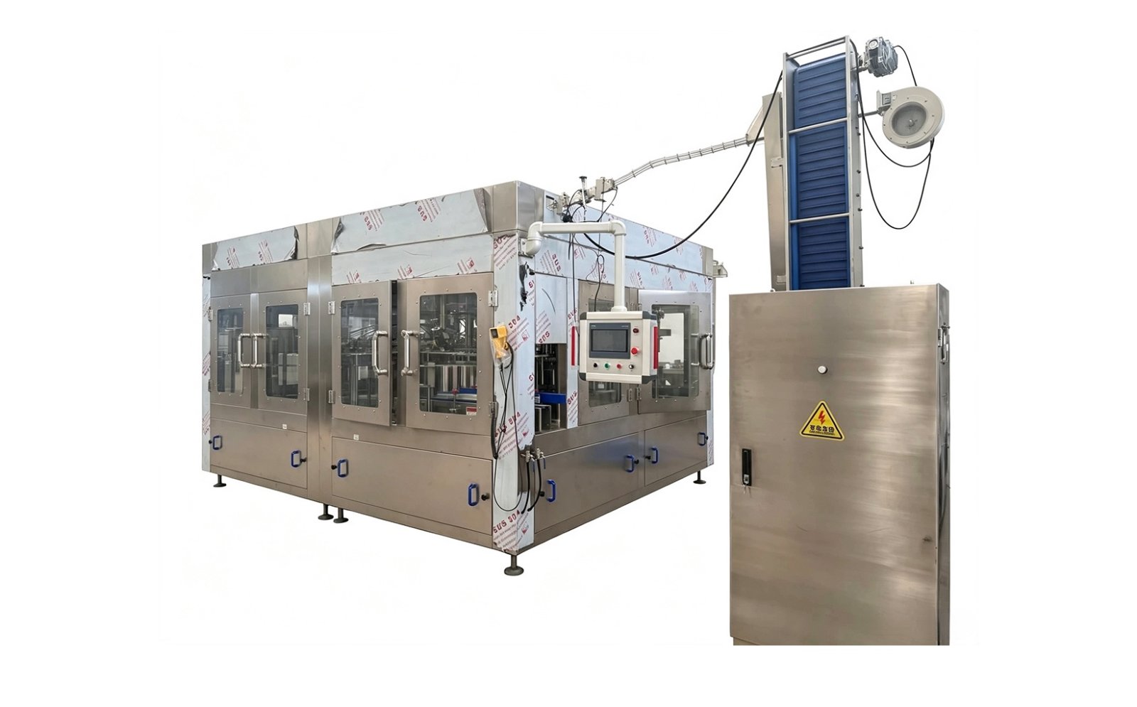
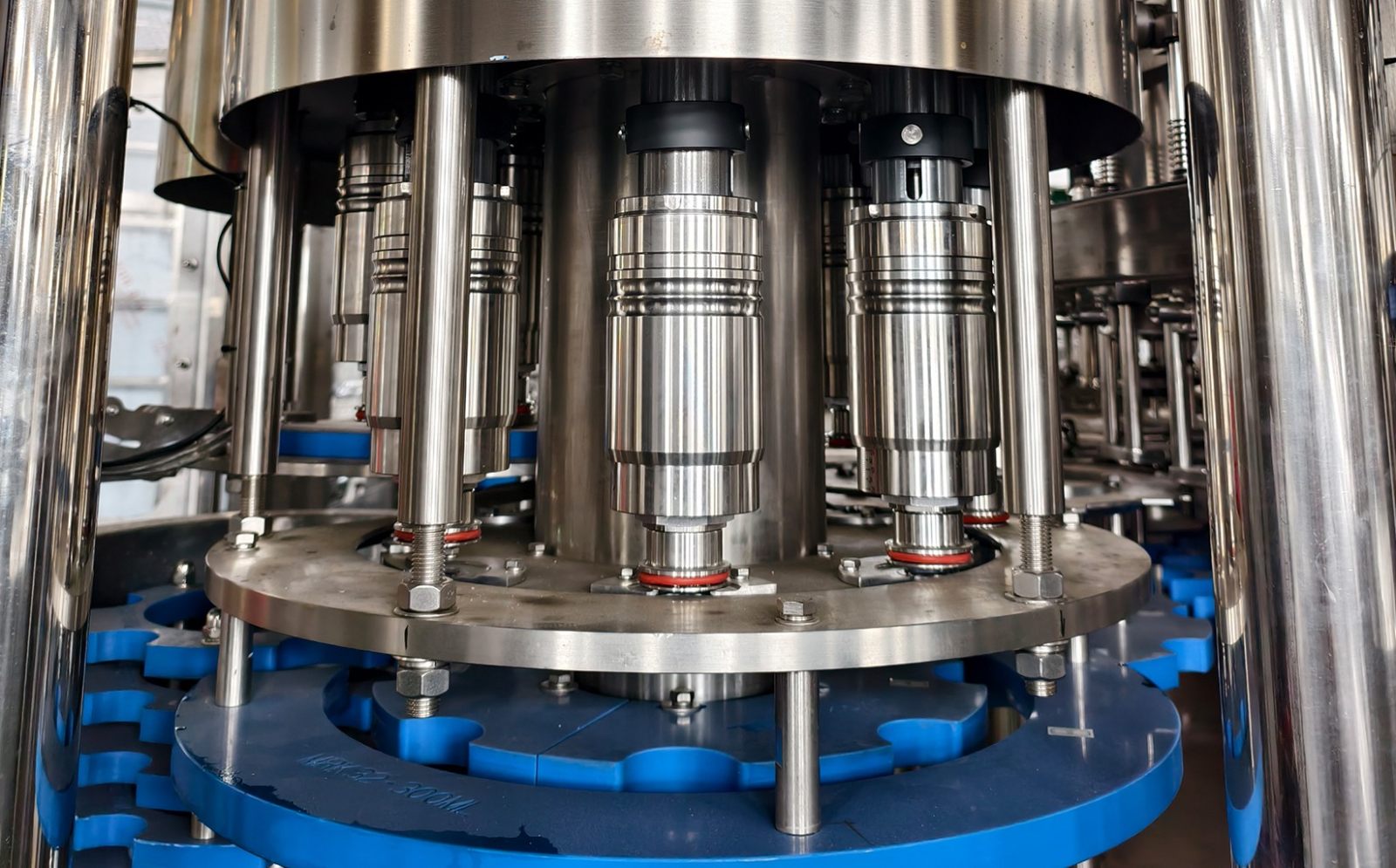
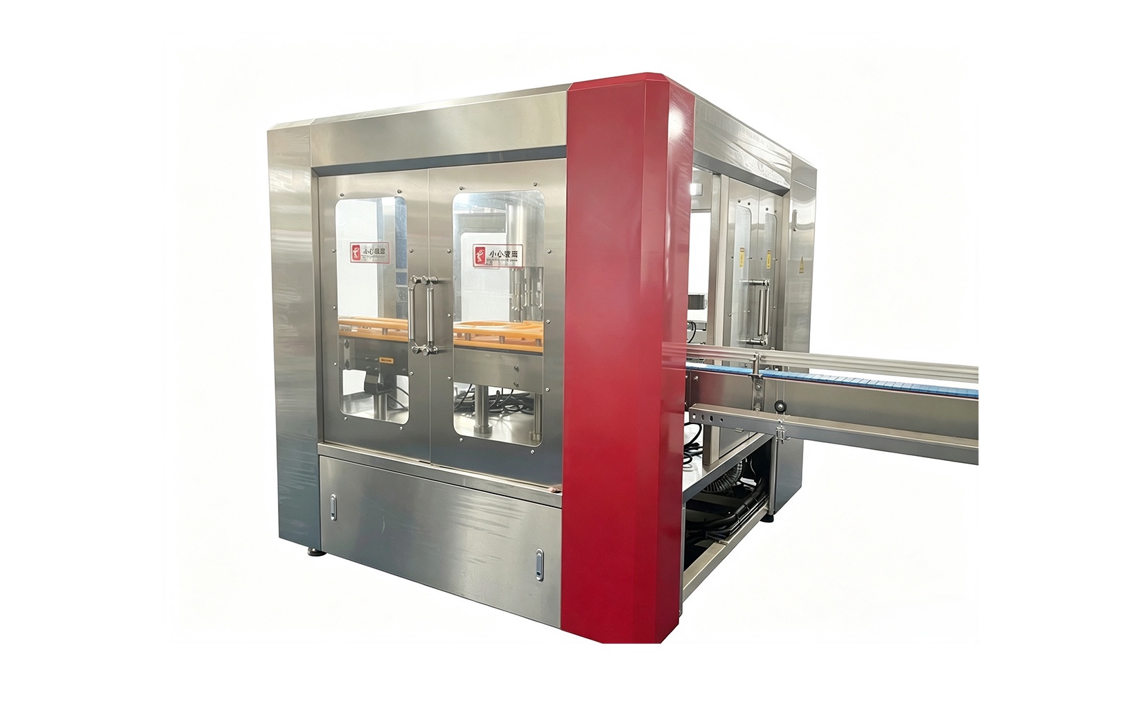
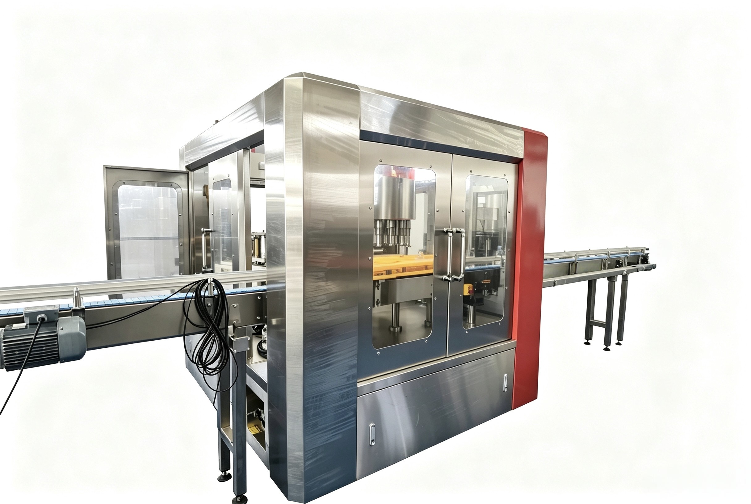
Carbonated drink filling machine

Product Value
01
Excellent gas retention: Isobaric filling minimizes CO₂ loss, ensuring ample carbonation in the finished product and reducing waste.
02
High level of automation: Integrates bottle rinsing, filling, and capping into a single unit, reducing labor requirements and enabling continuous, high-volume production.
03
Superior sealing performance: Features pressure-resistant piping and valve assemblies designed to prevent leaks and meet the pressure requirements of carbonated beverage production.
04
Strong compatibility: Supports various PET bottle specifications and allows for quick, convenient changeovers between different products.
Applicability boundaries

Suitable products
Carbonated beverages, sparkling water, soft drinks, and other CO2-infused drinks.

Suitable containers
PET plastic bottles; glass bottles require a customized machine model.

Required auxiliary equipment
Carbonator (beverage mixer), stable gas supply, chilled water cooling system, and a food-grade workshop environment.
Working Principle
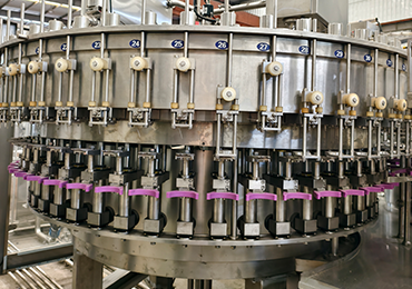
After the inner walls of the bottles undergo sterile rinsing at the rinsing station, they are conveyed to the filling station.
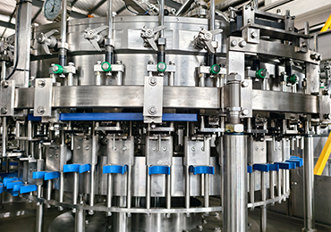
The bottles are first pre-pressurized with carbon dioxide to match the pressure in the product tank; once the pressure is balanced, the product flows into the bottles driven by the tank pressure.
Upon completion of filling, the pressure is relieved and the gas vented before the bottles disengage from the filling valves.
The bottles are then transported to the capping station for cap placement and tightening, after which the finished products are discharged. The entire process maintains a sealed, pressurized environment to prevent gas loss.
Core components
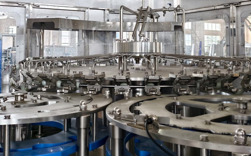
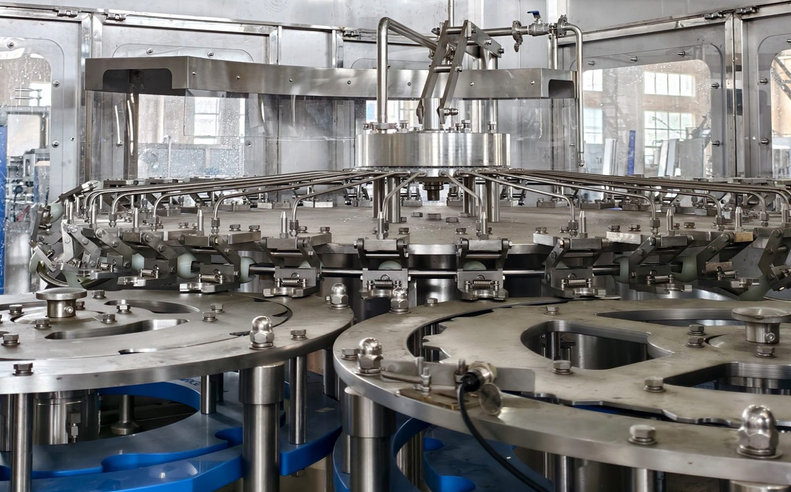
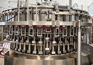
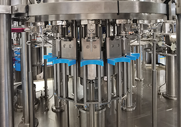
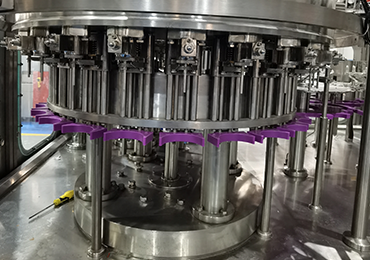
Bottle rinsing gripper assembly
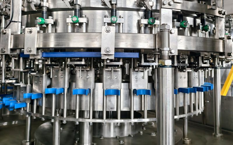
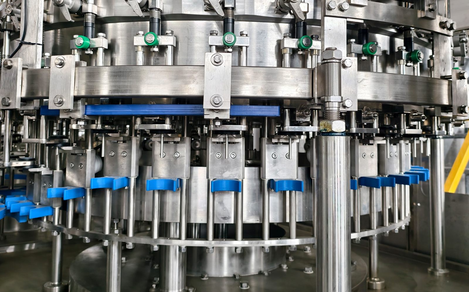
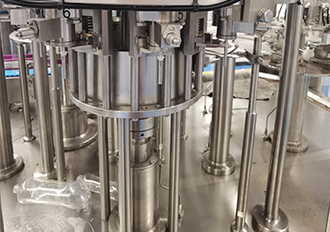
Isobaric filling valve assembly (including gas return and pressure relief lines)
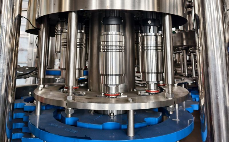
Capping head assembly
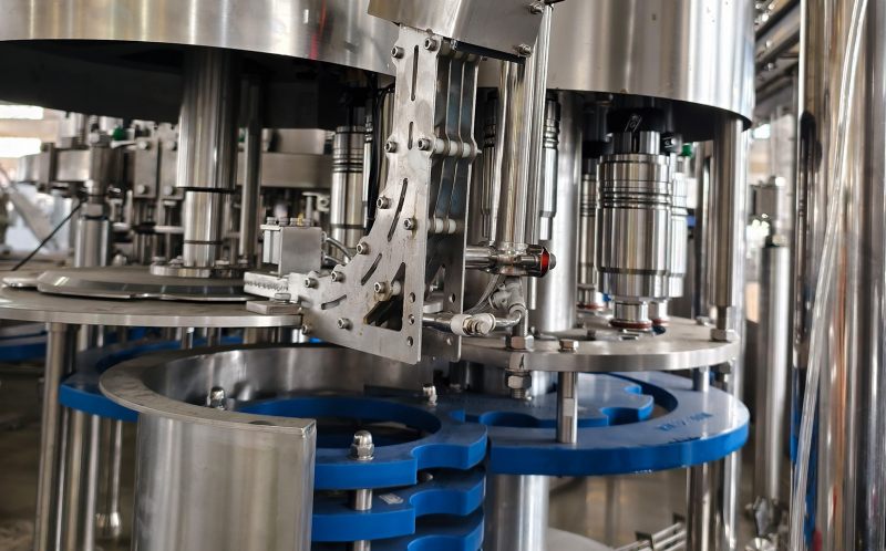
Starwheel, infeed/discharge feed screws, and liquid supply system
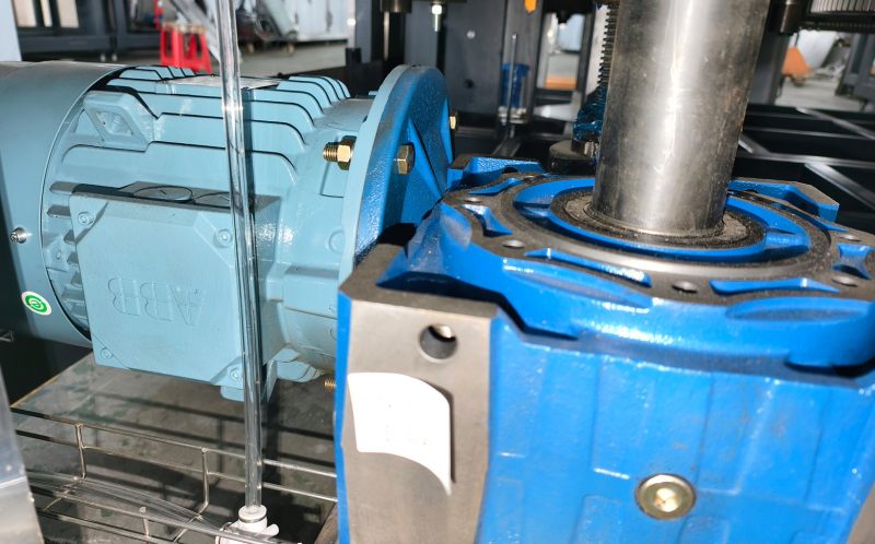
ABB motor system and pressure monitoring instruments
Optional
Online cap sterilization
CIP (Clean-in-Place) connection port
Fully enclosed protective housing
Variable-frequency speed control upgrade
HMI touchscreen upgrade
Changeover/Cleaning/Maintenance
Changeover
1. Adjust the spacing of the infeed/outfeed screws and star wheels to match the bottle diameter.
2. Adjust the height of the rinsing grippers and filling stations to match the bottle height.
3. Fine-tune the capping head height and torque.
4. Calibrate product tank pressure and filling time parameters; conduct test runs to verify liquid levels and carbonation content.
Cleaning
At the end of each production day: Perform CIP (Clean-in-Place) procedures, circulating caustic solution and hot water to clean the product tank and all piping.
Routine Maintenance
Replace wear parts such as filling valve seals and gripper pads; calibrate pressure gauges and check the lubrication of drive components.
Inconsistent filling levels?
Causes include fluctuations in product tank pressure, blockages in the gas return line, deformed bottle necks, or debris jamming the filling valve. Check the air supply and CO₂ pressure, clean the gas return passage, reject defective bottles, and disassemble/clean the filling valve.
How long does it take to switch bottle specifications?
If the bottle neck finish remains the same and only the height or diameter changes, a skilled operator takes 20–35 minutes.
What auxiliary equipment is required to put the system into operation?
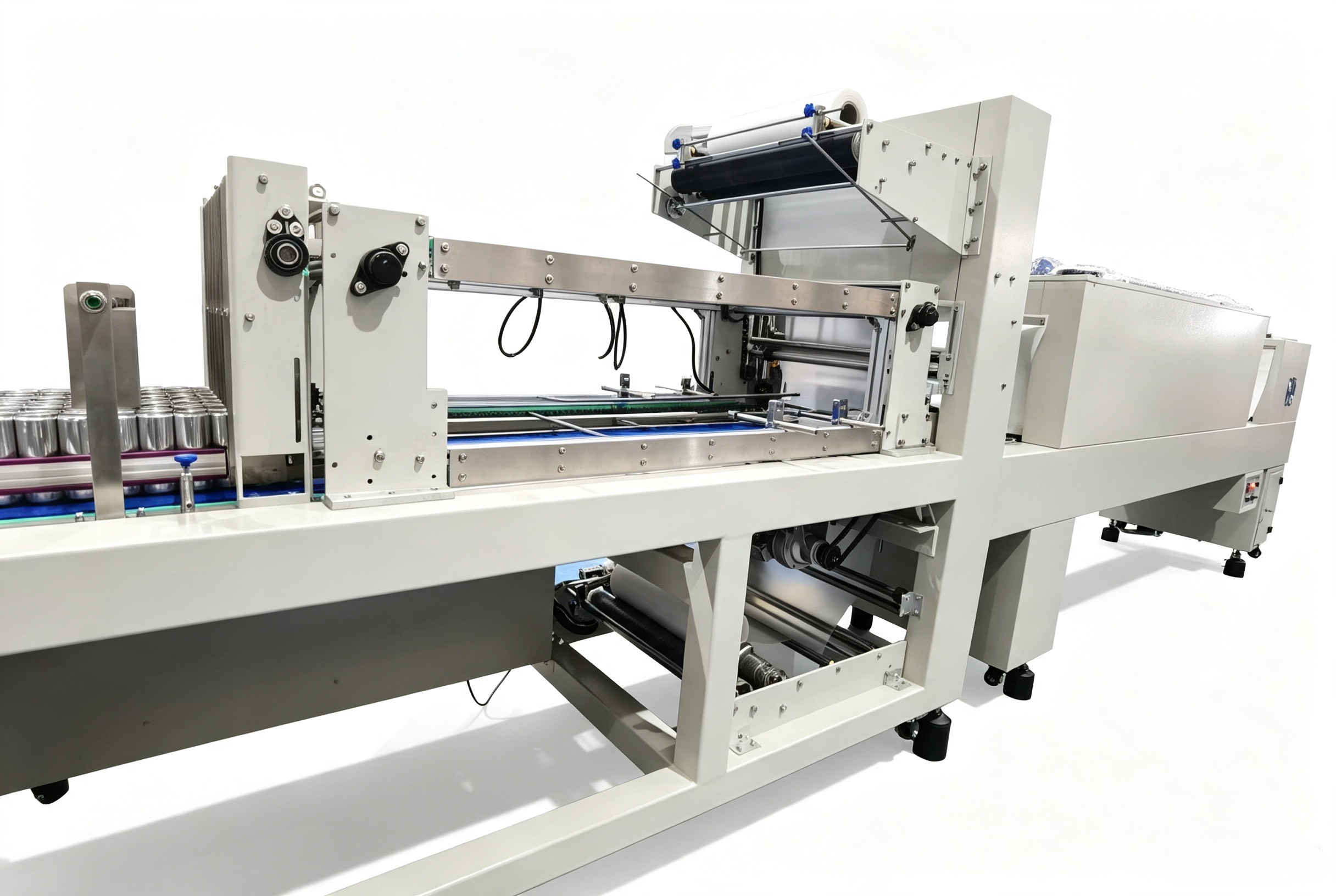
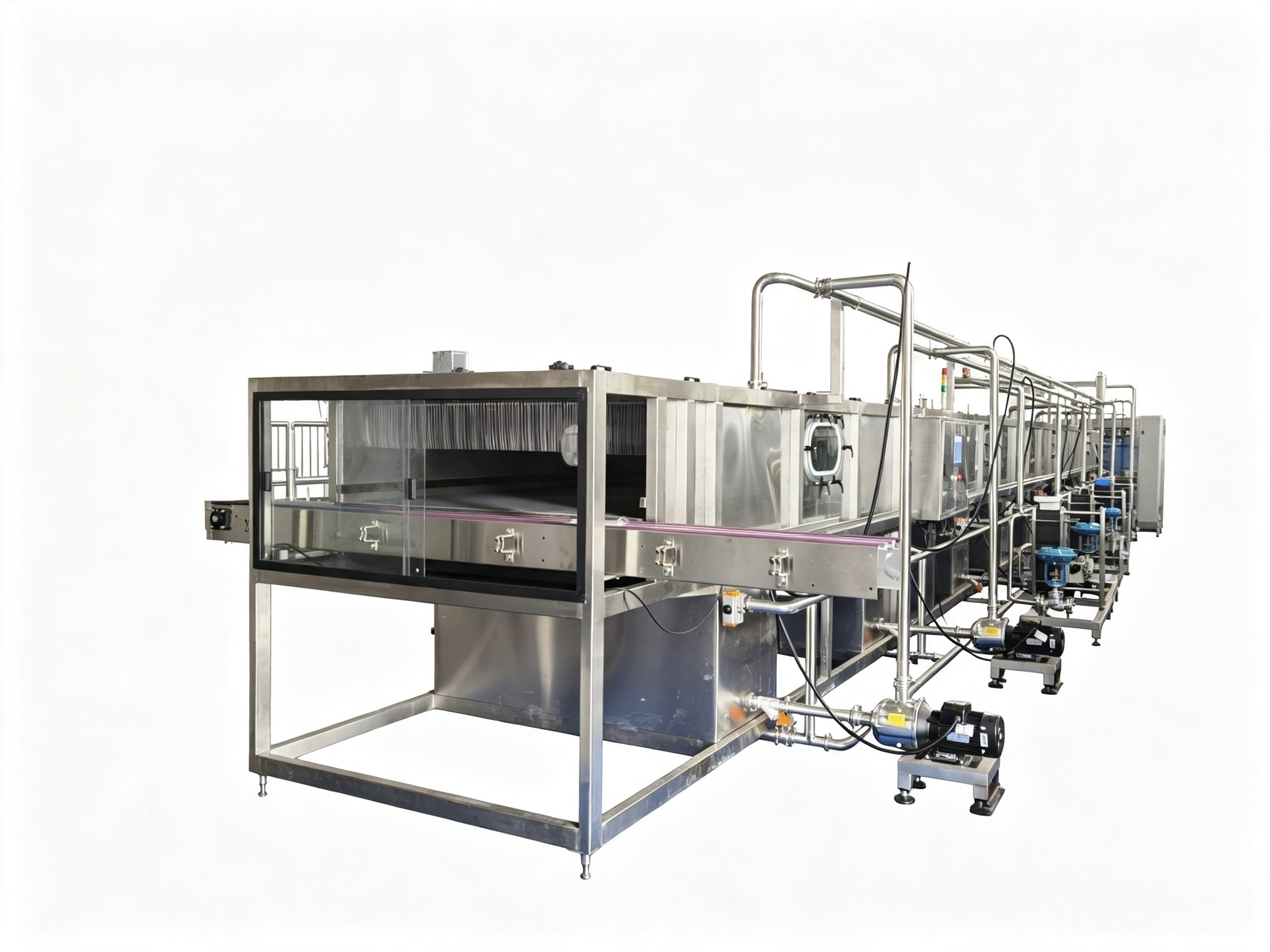
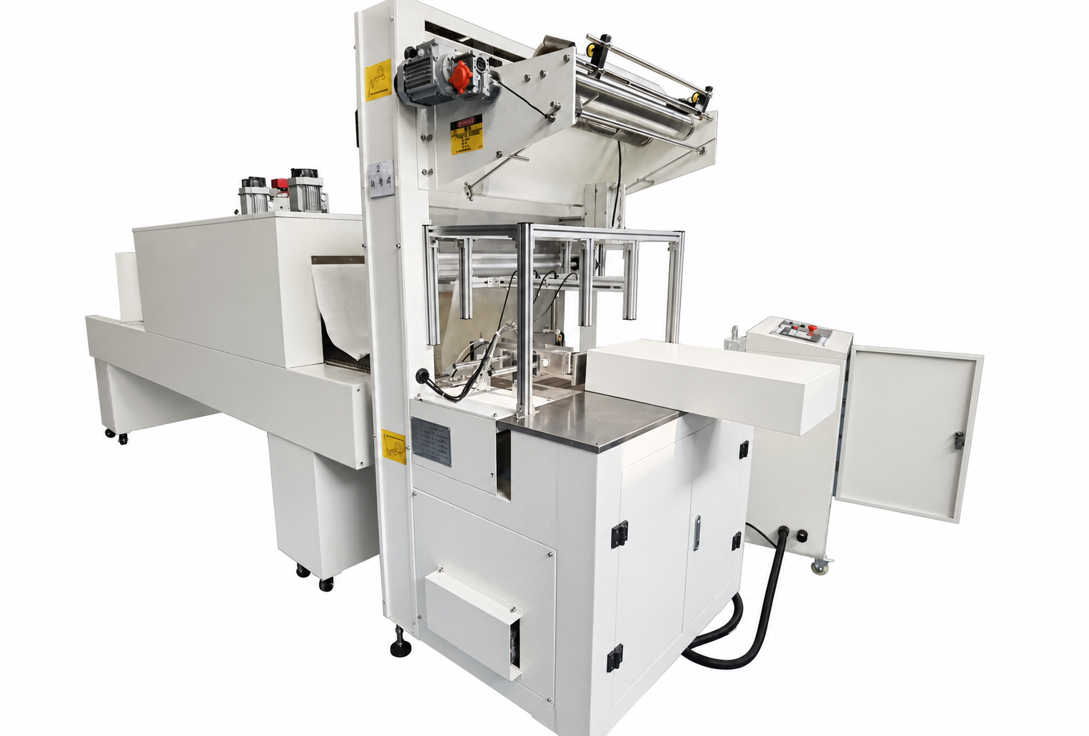
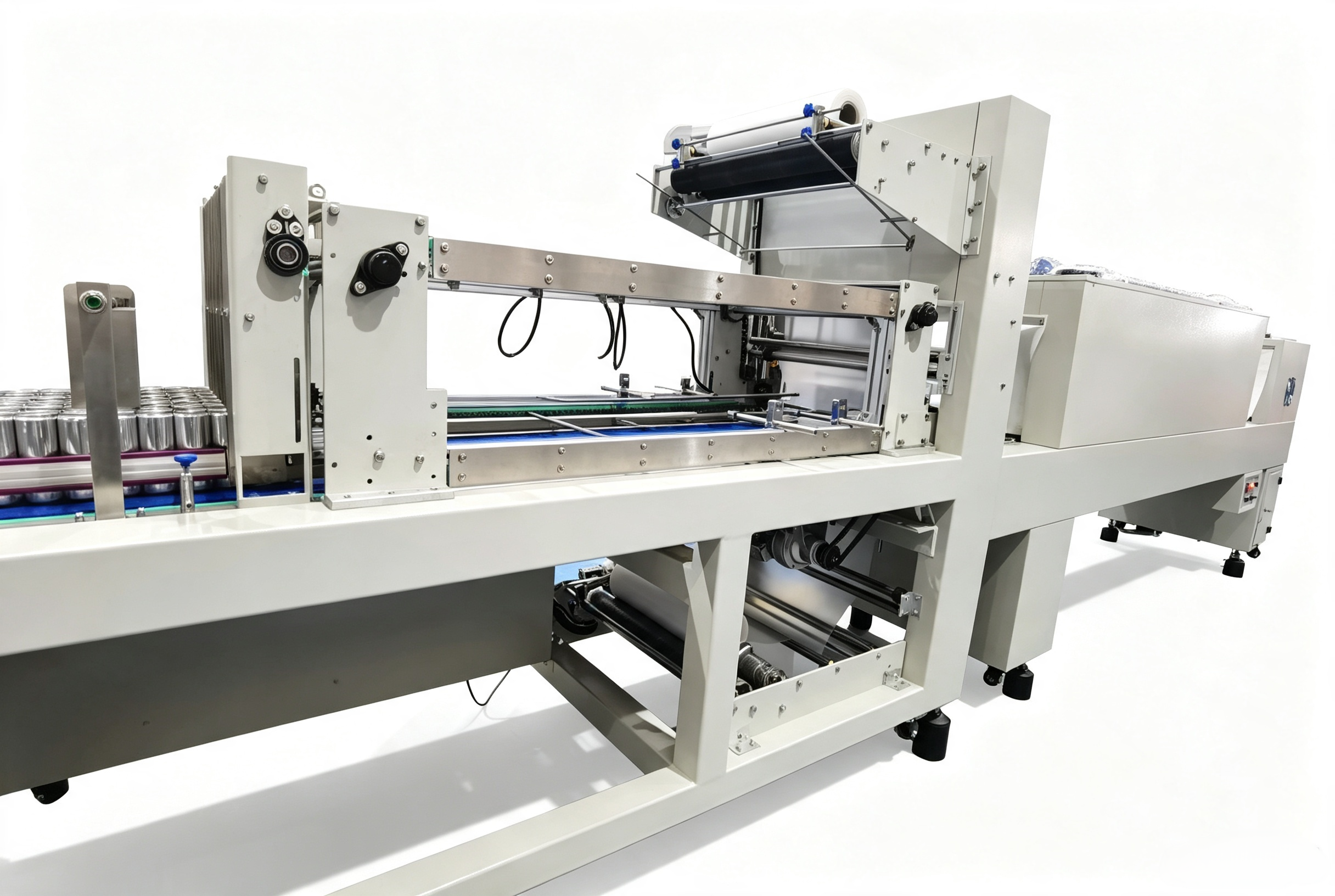
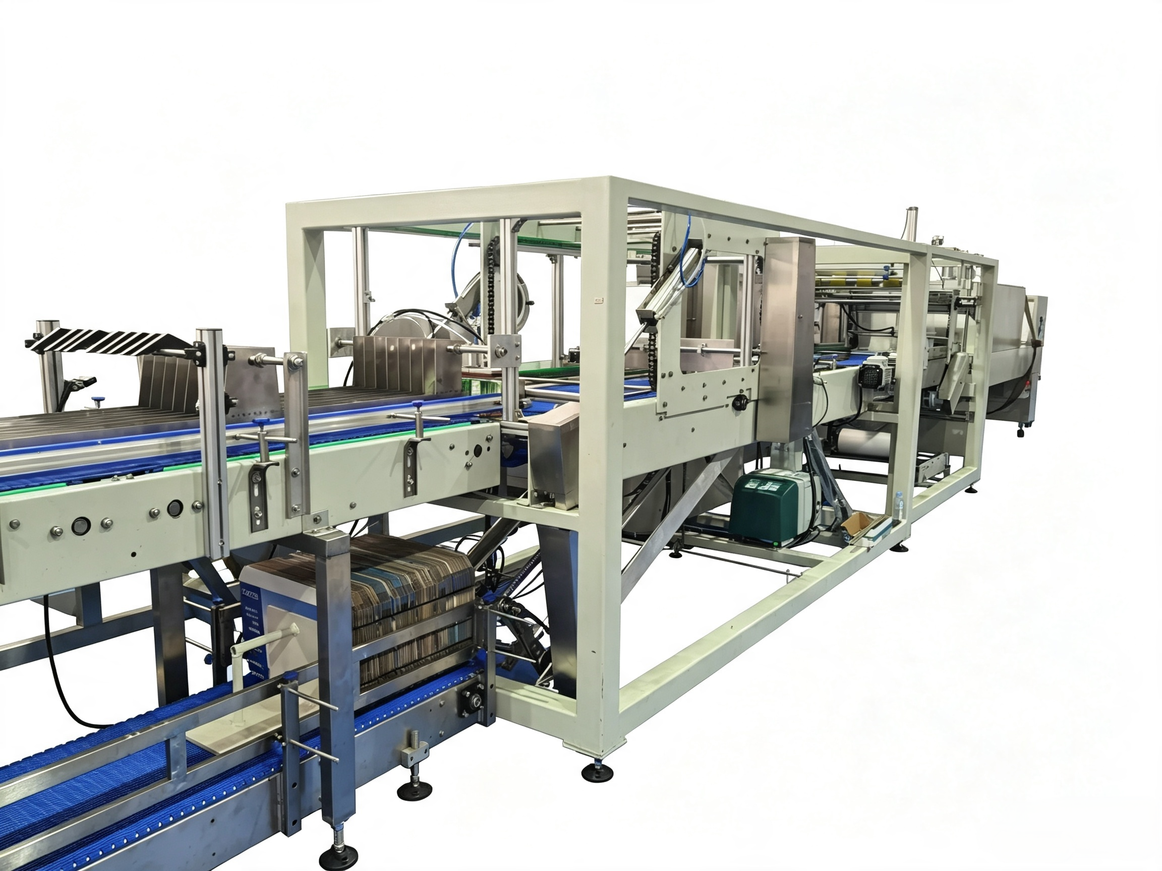
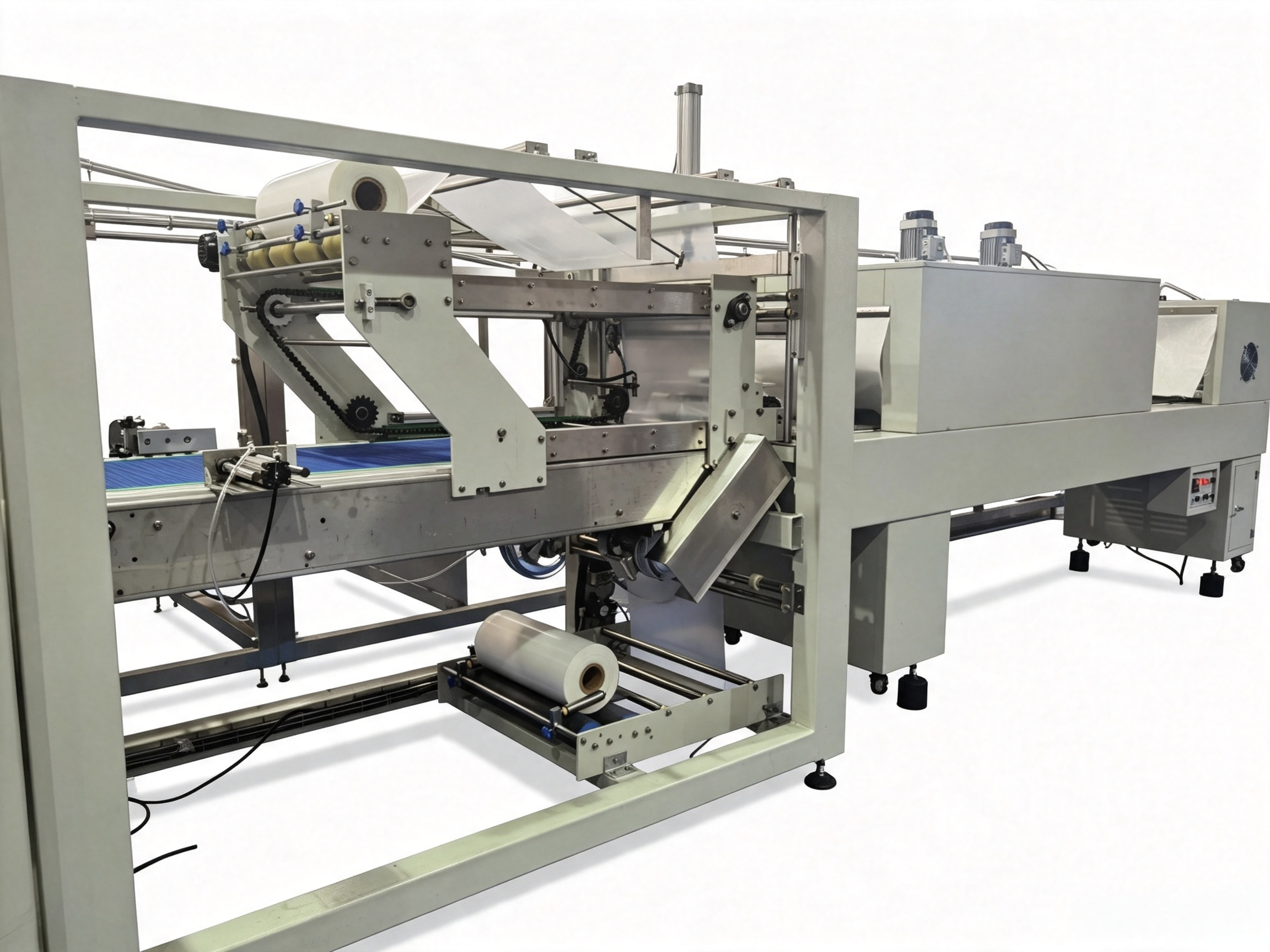
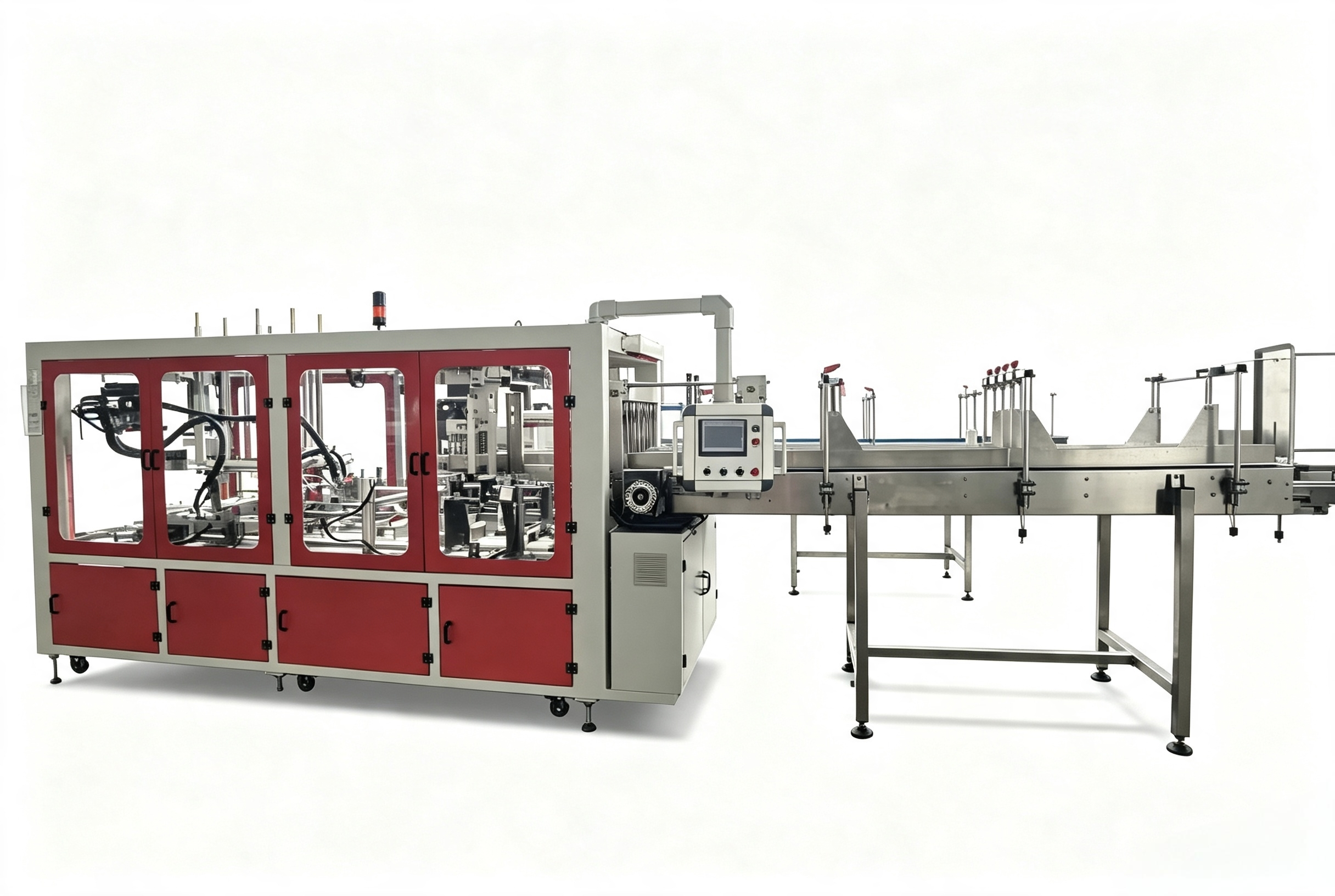
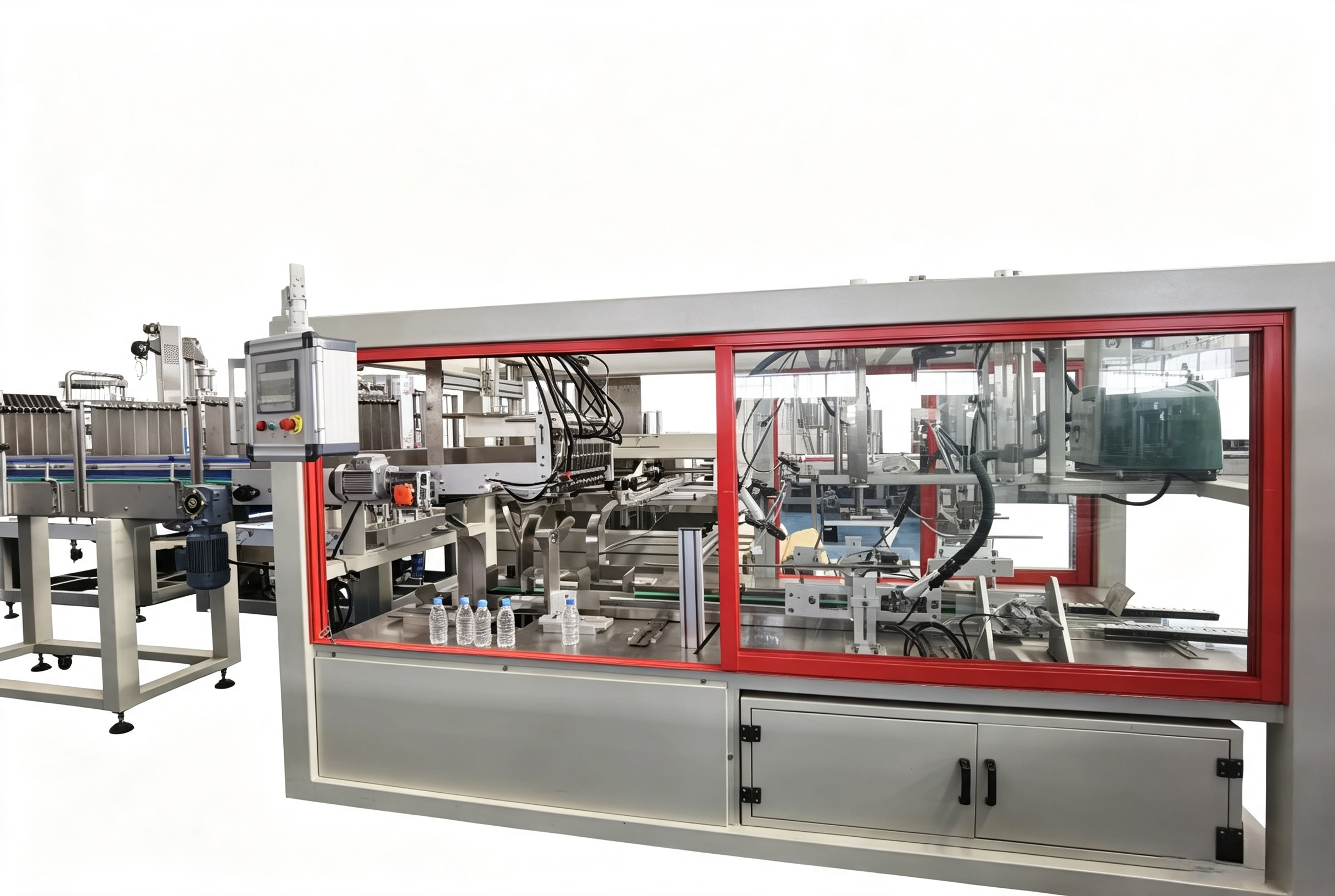
A beverage mixer (carbonator), chiller unit, air compressor, and CO₂ cylinders/supply system. Optional equipment such as a blow molding machine, air dryer, inkjet coder, labeling machine, and shrink wrapper can be added to form a complete production line.
What precautions should be taken for CIP (Clean-in-Place) cleaning?
Release the CO₂ pressure from the tank before starting the CIP cycle; ensure the full sequence of caustic washing and hot water rinsing is completed; drain the pipelines after cleaning to prevent residual product from fermenting. Never perform CIP cleaning while the system is pressurized.
Select the Suitable Model
 BDGF14125Inquire Now
- BDGF18186-for-beerInquire Now
- DCGF404012Inquire Now
- DCGF884Inquire Now
- DCGF14125Inquire Now
- DCGF18186Inquire Now
- DCGF505015-filling-with-electronicInquire Now
- DCGF323210Inquire Now
Related Product Recommendations
 Liner Type PE Film Wrapping MachineLearn More →
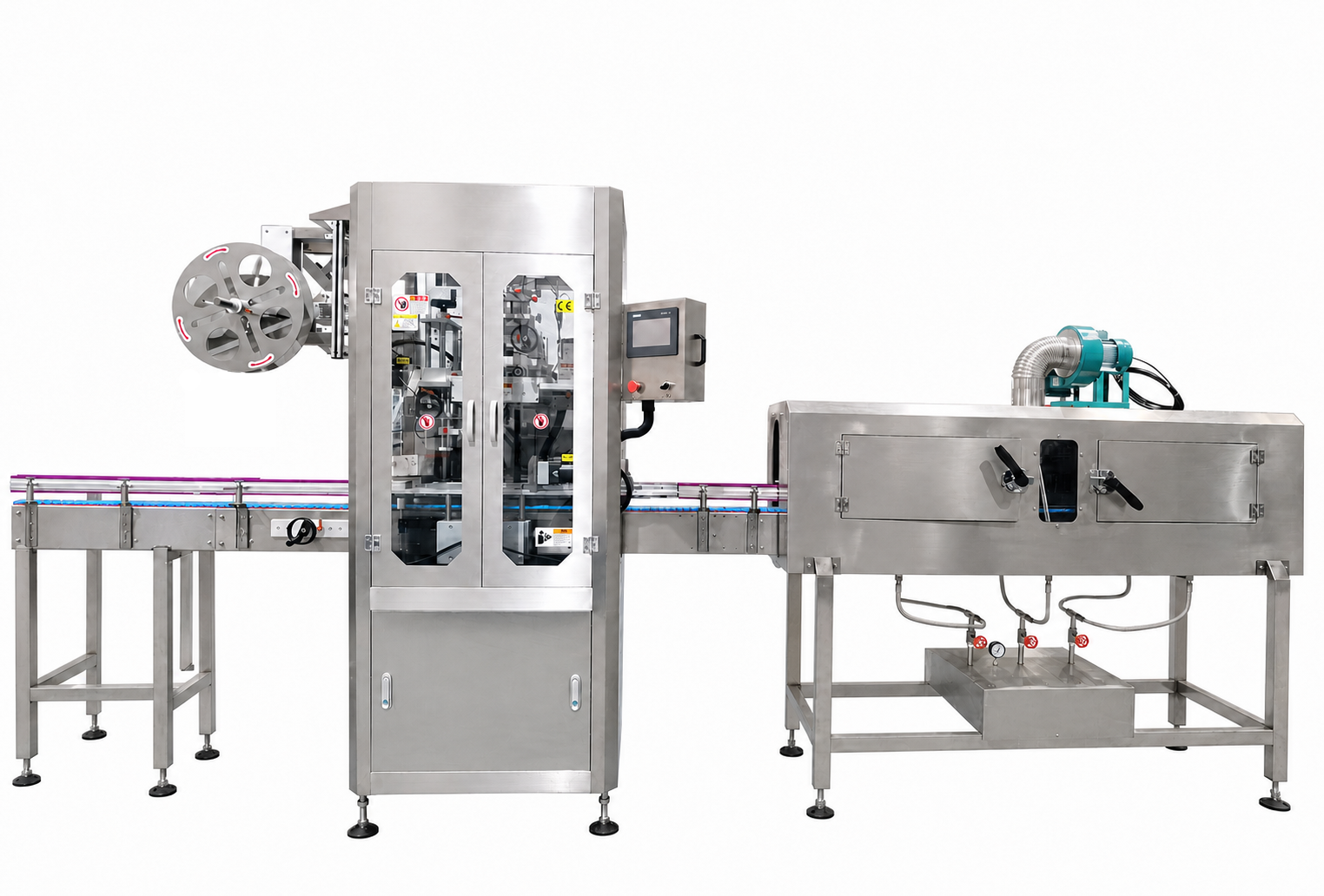
 Warming TunnelLearn More →
 Laser PrinterLearn More →
- Blow DryerLearn More →
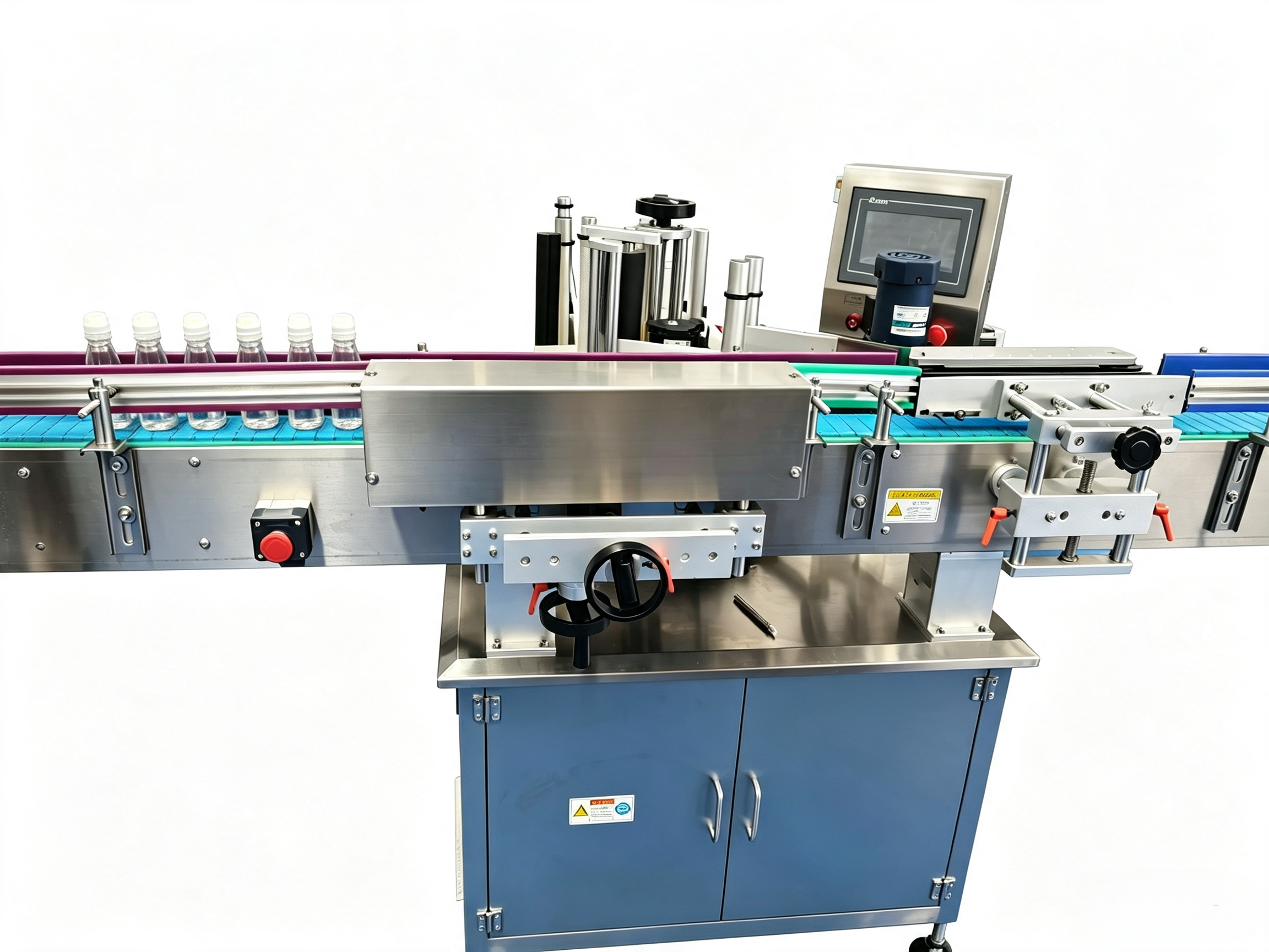
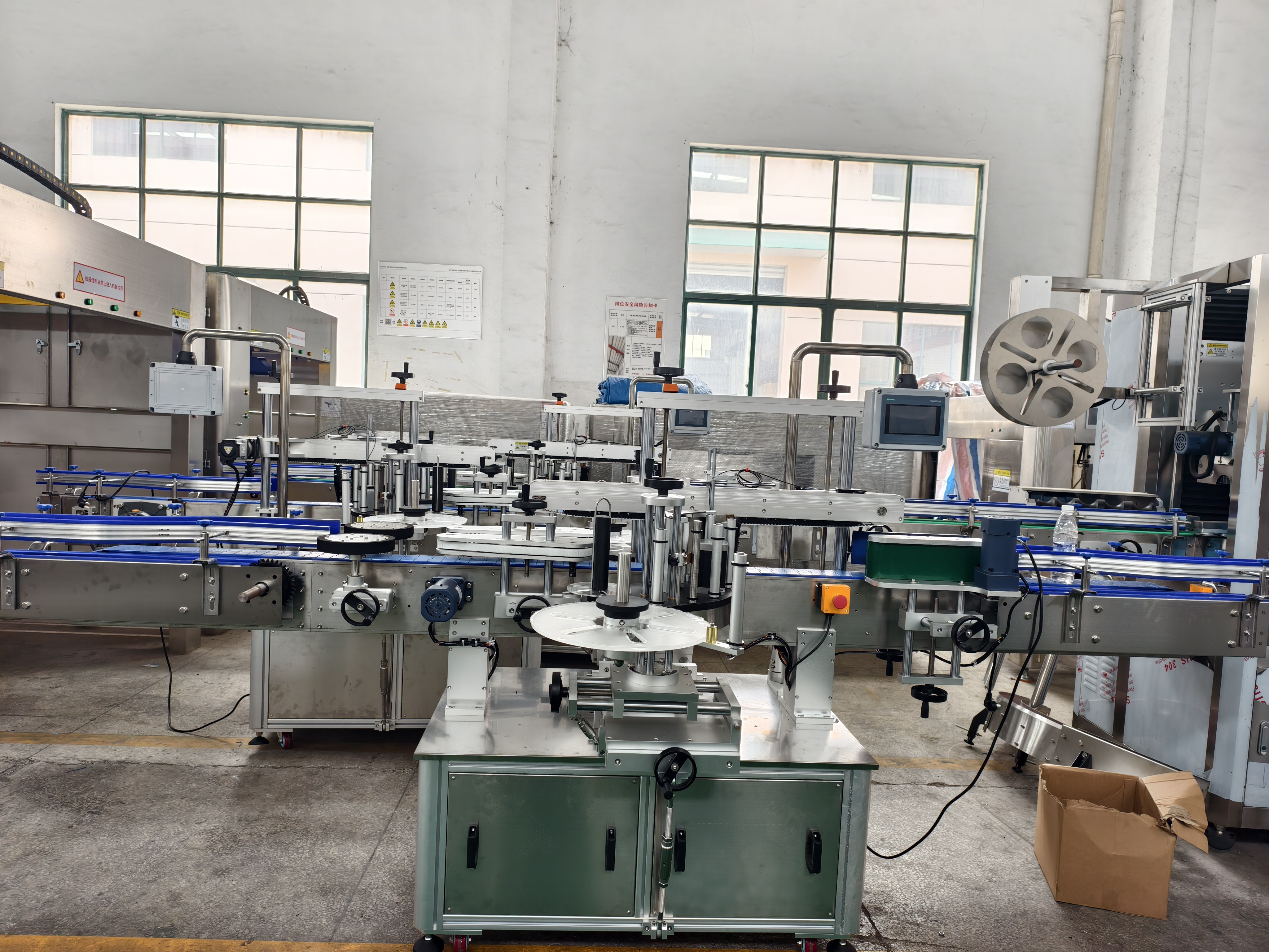
 opp labeling machine oppLearn More →
 PE film packing machineLearn More →
- Half tray packing machineLearn More →
- Sticker labeling machineLearn More →
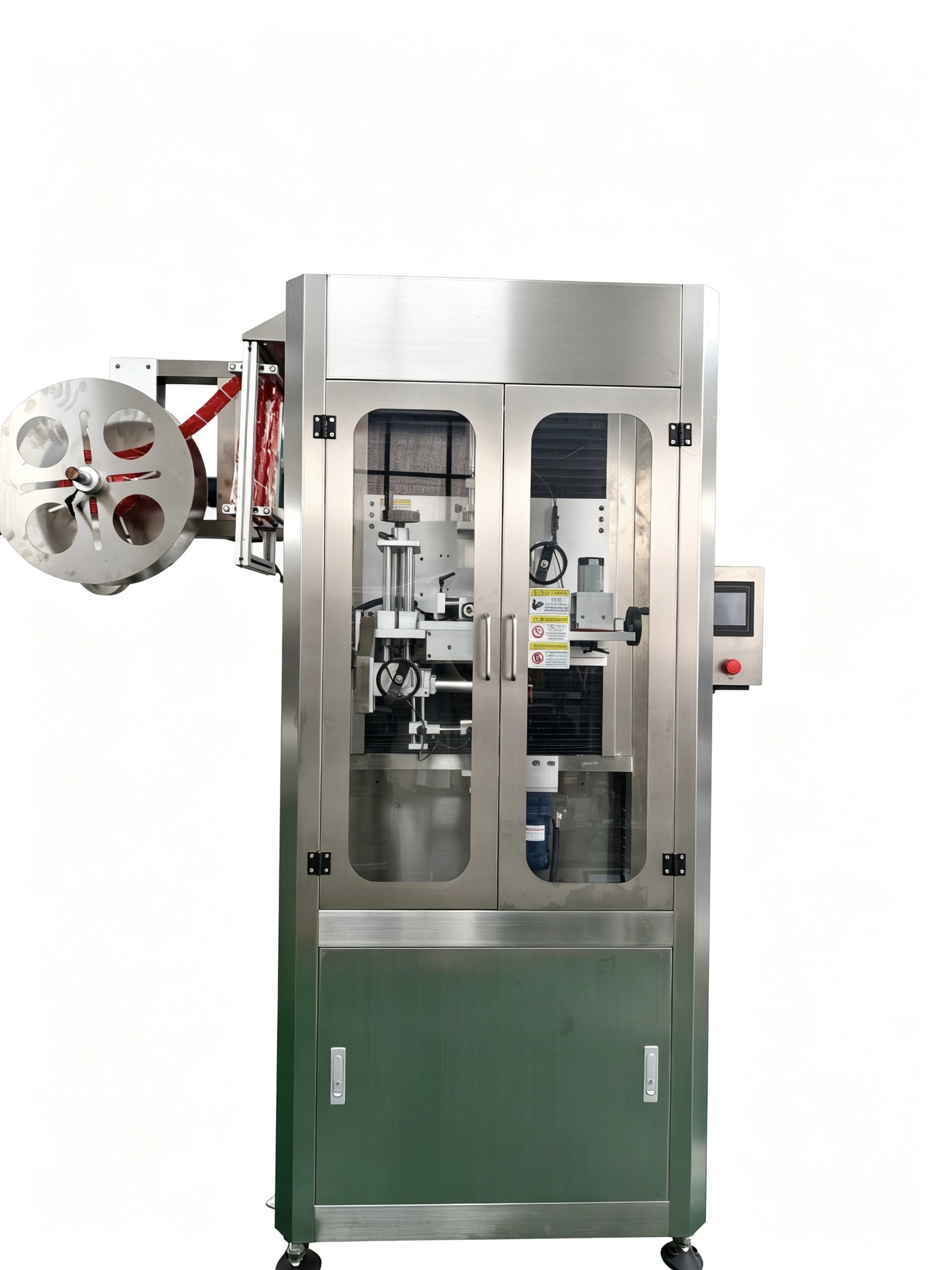
 Sleeve and shrink labeling machineLearn More →
- Carton packing machineLearn More →
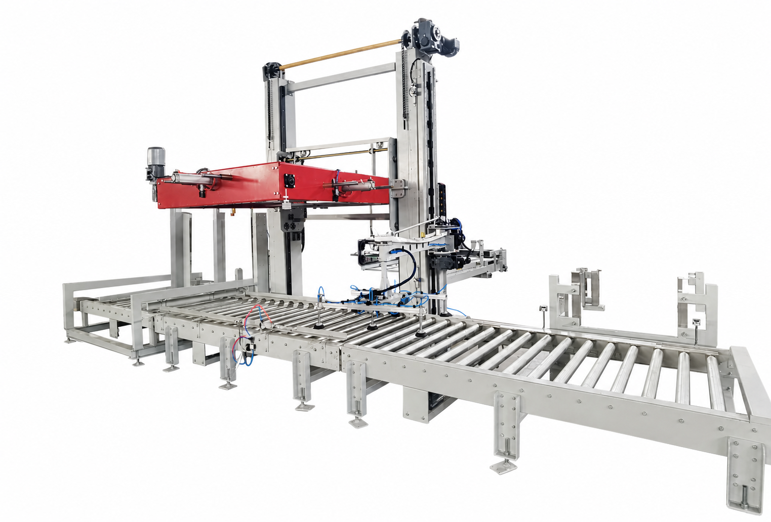
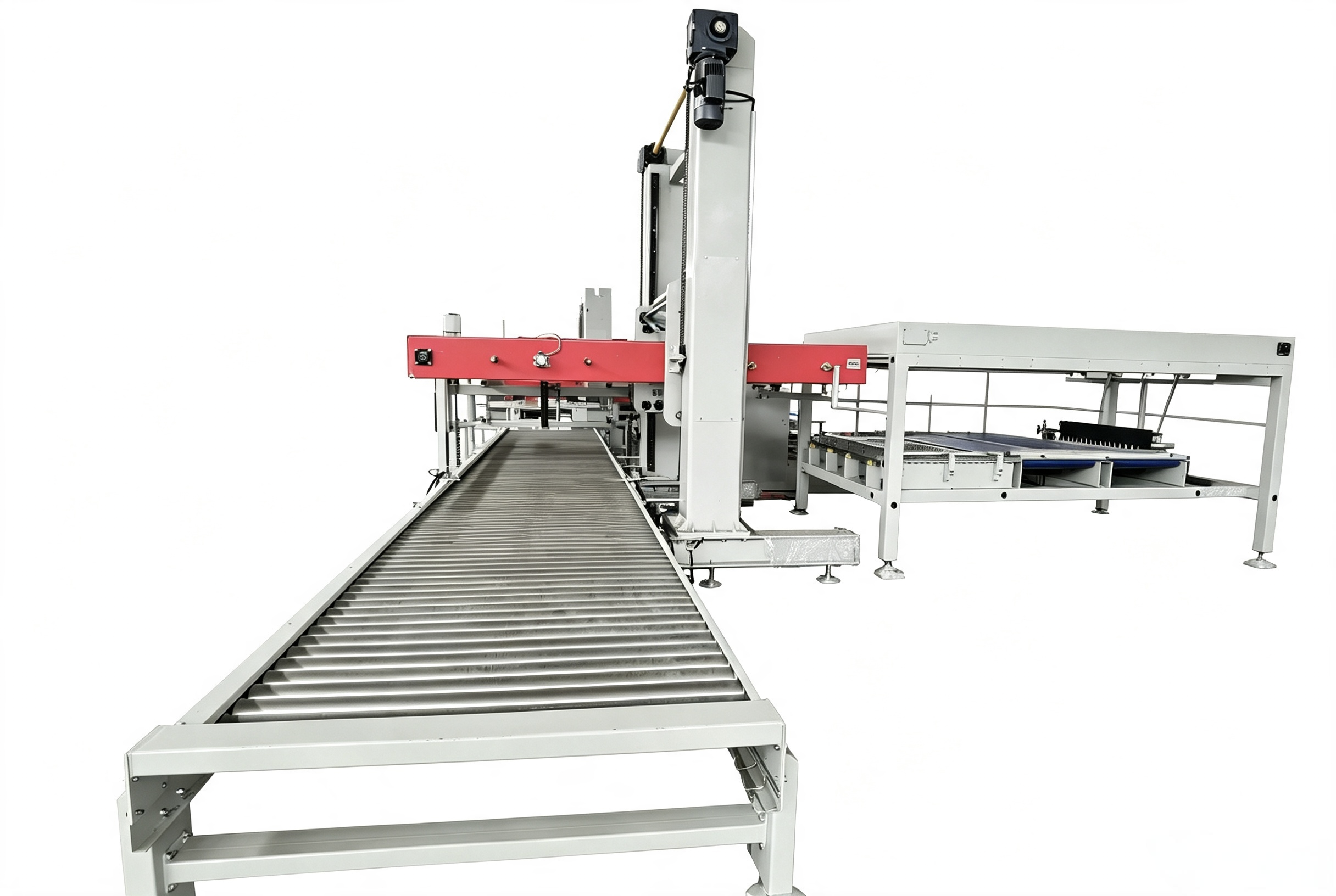
- PalletizerLearn More →
- Reverse osmosisLearn More →
Contact Us
Complete 2 easy steps below to get your factory matrix and a complimentary factory layout design within 24 hours.
Request Factory Price & Factory Layout Within 24h
Request Factory Price & Factory Layout Within 24h